
A Centrifugal Fan is a practical machine for moving air through buildings, factories, and process equipment. Unlike an axial fan, it turns airflow through a right-angle path. Air enters near the impeller’s center, then leaves through the casing under higher pressure. Picture air pulled into a rotating wheel and guided toward a discharge outlet. That simple path explains its usefulness in ventilation, dust collection, cooling, and combustion systems.
The U.S. Department of Energy’s Improving Fan System Performance: A Sourcebook for Industry identifies fans as major industrial electricity users. It also emphasizes system design, control, and maintenance rather than fan selection alone. The International Energy Agency’s Energy Efficiency 2023 report states that buildings consume about 30% of global final energy. Efficient air movement therefore matters beyond the equipment room. AMCA Publication 210 and ANSI/AMCA Standard 210 provide recognized methods for measuring fan airflow, pressure, and performance. These standards help engineers compare tested results with operating requirements.
Real installations are rarely perfect. Duct leakage, clogged filters, oversized motors, and poorly adjusted dampers can reduce efficiency. Sometimes, a quieter fan performs better than a stronger one. The numbers can surprise you. A centrifugal fan may deliver excellent pressure, yet waste energy when operating far from its design point. This guide explains the impeller, housing, pressure conversion, fan curves, and common control methods. It also considers practical selection issues, including noise, maintenance access, motor efficiency, and variable-speed operation. Some simplified explanations cannot represent every installation. That limitation deserves attention. Performance depends on the whole system, not the fan alone.
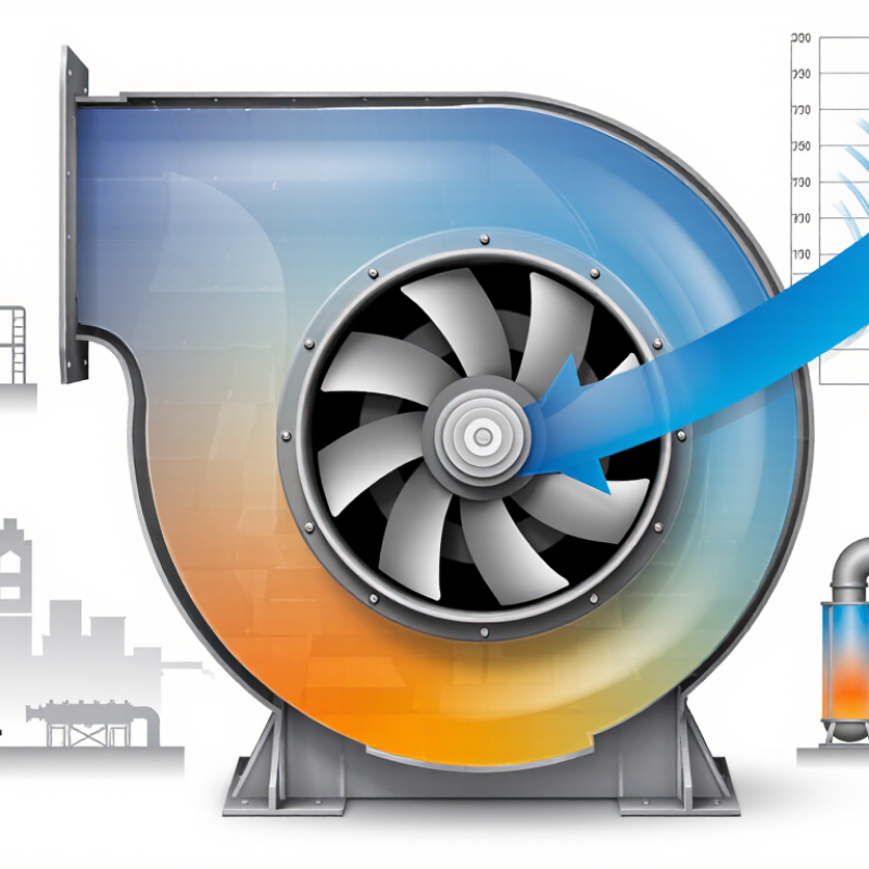
A centrifugal fan is a mechanical device that moves air or gas by changing its direction and increasing its pressure. Unlike an axial fan, it draws air into the center of a rotating wheel and pushes it outward through a housing. This radial movement gives the fan its common alternative name, radial fan. The wheel usually contains curved blades, a hub, and a shaft connected to a motor. The surrounding casing guides airflow toward the outlet.
During operation, the motor turns the wheel at a controlled speed. Air enters through the inlet near the shaft, where the rotating blades capture it. Centrifugal force and blade geometry drive the air toward the outer edge. As air leaves the wheel, part of its velocity changes into static pressure inside the casing. The outlet then directs pressurized air into ductwork, filters, heaters, or process equipment. It can handle resistance better than many simple propeller fans.
Performance depends on wheel size, speed, blade shape, air density, and system resistance. A technician should check the fan curve, airflow requirement, pressure loss, temperature, and noise level before selection. Poorly matched equipment may waste energy or deliver less air than expected. I have found that installation details matter more than specifications alone; a sharp duct bend near the outlet can disturb flow and create vibration. The term “centrifugal force” is useful in practice, although engineers often explain pressure rise through rotating-flow principles. That distinction is easy to overlook.
A centrifugal fan uses a rotating impeller to draw air into the center and discharge it radially through the housing. The chart shows the fan affinity laws for a constant impeller diameter: airflow changes in direct proportion to speed, pressure changes with the square of speed, and power changes with the cube of speed.
Values are normalized to the performance at 100% rotational speed. These relationships are idealized engineering laws and assume the same fan geometry and similar operating conditions.
A centrifugal fan moves air by changing its direction and velocity. Air enters near the impeller’s center, or eye. Rotating blades then push the air outward through centrifugal force. The air leaves the impeller at high velocity and enters the scroll-shaped housing. This housing slows the airflow and converts part of its velocity pressure into static pressure. The process resembles water leaving a spinning bucket.
Fan speed strongly affects performance. According to AMCA engineering guidance, airflow changes roughly in direct proportion to speed. Pressure changes with the square of speed, while power changes with the cube.
A 10% speed reduction can therefore cut ideal power demand to about 73%. Real systems perform less neatly. Duct leakage, clogged filters, turbulence, and poor clearances can alter the result.
The U.S. Department of Energy’s fan-system guidance identifies fans as a significant electricity load, with fan systems representing about 23% of commercial building electricity use. That figure explains why operating points matter.
A technician checking a running installation may find the impeller moving plenty of air, but against excessive resistance. The motor works harder. Noise rises. Useful airflow may still disappoint.
AMCA Publication 210 provides standardized methods for measuring fan airflow, pressure, and efficiency, yet field conditions remain imperfect. The calculation is only as reliable as the measurements.
What Is a Centrifugal Fan and How Does It Work?
What Are the Main Parts of a Centrifugal Fan?
A centrifugal fan has several parts that work as one airflow system. The impeller is the rotating core. Its curved blades capture air near the center and push it outward through centrifugal force. The fan housing surrounds the impeller and guides air toward the discharge outlet. Its spiral shape helps convert some air velocity into useful pressure.
The inlet directs air into the impeller eye. The outlet releases air into a duct or open space. A shaft connects the impeller to the motor, while bearings support smooth rotation. Some fans use direct drive, while others use belts and pulleys. Each arrangement affects maintenance, speed control, and efficiency. Guards cover moving parts and reduce contact risks. Small details matter.
From practical inspections, loose belts often cause unusual noise and reduced airflow. Dust on blades can also unbalance the impeller. I have seen a fan appear powerful while delivering weak airflow because its duct was restricted. That mistake is easy to miss. Seals, flexible connectors, and vibration mounts deserve attention too. A small air leak can waste pressure. Regular checks should include bearing temperature, belt tension, blade cleanliness, and mounting bolts. No inspection is perfect. Measurements still matter.
| Main Part or Concept | Primary Function | How It Works | Common Construction or Configuration | Operational Importance |
|---|---|---|---|---|
| Impeller | Adds energy to the air or gas. | Rotating blades accelerate incoming air outward by centrifugal force. | Backward-curved, forward-curved, or radial blades; may be single-inlet or double-inlet. | Blade shape affects airflow, pressure, efficiency, noise, and power demand. |
| Fan Casing | Collects and redirects the moving air. | The scroll-shaped housing gradually converts part of the air velocity into static pressure. | Welded or formed steel, aluminum, or corrosion-resistant alloys. | A properly designed casing reduces turbulence and supports stable discharge flow. |
| Inlet Nozzle or Cone | Guides air smoothly into the impeller. | Its tapered geometry reduces entry losses and helps distribute air evenly across the impeller eye. | Circular or rectangular inlet designs, depending on the system connection. | Poor inlet alignment can increase turbulence, noise, and energy consumption. |
| Outlet or Discharge | Delivers pressurized air to the duct or process equipment. | Air leaves the casing through an outlet positioned according to the required installation layout. | Top, side, or angled discharge arrangements are commonly used. | Outlet size and direction influence system resistance and installation flexibility. |
| Shaft | Transfers rotational power to the impeller. | The shaft rotates with the impeller and must withstand torque, bending forces, and operating speed. | Machined steel or other engineered metal alloys, depending on the application. | Correct alignment and balance help prevent vibration and premature component wear. |
| Bearings | Support the rotating shaft. | Bearings reduce friction while maintaining the shaft position during operation. | Ball, roller, or sleeve bearings may be used according to load, speed, and service conditions. | Lubrication, temperature, and vibration are important maintenance indicators. |
| Motor and Drive | Provides the mechanical power needed for rotation. | The motor drives the impeller directly or through belts, pulleys, or another transmission arrangement. | Direct-drive and belt-drive configurations are common. | Fan speed strongly affects airflow, pressure, noise, and power consumption. |
| Base and Frame | Supports and stabilizes the fan assembly. | The frame transfers static and dynamic loads to the mounting surface. | Fabricated steel frames, mounting rails, or vibration-isolated bases. | A rigid and level installation helps maintain alignment and minimize vibration. |
| Inlet and Outlet Guards | Protect personnel and equipment from rotating or moving components. | Guards restrict access to the impeller and exposed drive parts while allowing airflow. | Perforated metal, expanded metal, or protective mesh. | Guards should remain securely installed during operation and maintenance. |
| Access Panel | Allows inspection and cleaning of internal components. | Removable or hinged panels provide access to the impeller, casing, and internal surfaces. | Bolted, latched, or gasketed panels are used according to the pressure and hygiene requirements. | Regular inspection helps identify dust buildup, corrosion, imbalance, and wear. |
| Airflow Principle | Moves air from the inlet to the discharge system. | Air enters near the impeller center, moves radially outward, and exits through the casing at a higher pressure. | The process is based on centrifugal acceleration and pressure recovery. | Centrifugal fans are suitable for applications requiring moderate to high pressure against system resistance. |
| Key Performance Factors | Determine fan capacity and operating efficiency. | Airflow, static pressure, fan speed, impeller diameter, air density, and system resistance interact to define performance. | Performance is normally evaluated using fan curves and system curves. | Selecting a fan near its intended operating range can improve efficiency and service life. |
Centrifugal fans are classified mainly by blade shape, wheel design, and airflow purpose. A rotating impeller draws air through its center and pushes it outward. The housing then redirects that air toward the discharge outlet. Small details matter, including blade angle, speed, and operating pressure.
Forward-curved fans use many short blades that face the direction of rotation. They deliver high airflow at relatively low pressure and fit well in compact ventilation equipment. However, their power demand can rise sharply when resistance increases.
Backward-inclined fans have blades leaning away from rotation. They usually provide better efficiency and more stable operation.
Airfoil fans use shaped, hollow blades and can reduce turbulence, but they require cleaner air and careful maintenance.
Radial-blade fans use straight blades extending from the wheel. Their rugged design handles dust, moisture, and light particles better than airfoil designs. They often produce more noise and consume more energy. I have seen technicians choose them for dirty workshops, then regret ignoring sound levels.
Single-inlet fans draw air from one side, while double-inlet fans admit air from both sides and can move greater volumes.
Fan curves, filter condition, and duct resistance should guide the selection. A catalog label alone is not enough. Field measurements sometimes expose a mismatch between expected and actual performance.
A centrifugal fan pulls air into the center of a spinning impeller. The impeller turns the airflow outward, increasing its pressure. A curved housing then guides the air toward the outlet. This design handles resistance better than many axial fans. That matters when air must pass through filters, ducts, coils, or dampers.
Centrifugal fans are common in building ventilation systems, kitchens, workshops, and industrial exhaust lines. They remove warm air, smoke, dust, and process fumes from enclosed areas. In a factory, one fan may push air through a long duct with several bends. In a commercial kitchen, it can move greasy, heated air above cooking equipment. These fans also support air-handling units, drying equipment, tunnels, and dust-collection systems. The correct model depends on airflow, static pressure, temperature, noise limits, and the material carried. A fan can look powerful yet perform poorly if the duct is undersized. The choice is rarely perfect. Engineers often balance energy use, sound, maintenance, and installation space.
Tips: Check the fan curve before selecting equipment. Measure system resistance, not just room size. Inspect belts, bearings, guards, and vibration regularly. Dirty filters can quietly reduce airflow and increase energy use. If dust or moisture is present, confirm that the fan materials and construction suit the environment. Small oversights can become expensive.


